The Beam Analysis tool enables structural engineers to model simply supported and cantilevered beams, apply a variety of load types, and instantly visualize shear force diagrams (SFD), bending moment diagrams (BMD), and free body diagrams (FBD). Results can be exported as a formatted engineering report.
The Beam Analysis tool enables structural engineers to model simply supported and cantilevered beams, apply a variety of load types, and instantly visualize shear force diagrams (SFD), bending moment diagrams (BMD), and free body diagrams (FBD). Results can be exported as a formatted engineering report.
Prerequisites: An active account with the appropriate subscription tier is required to access certain features, including distributed loads, moment loads, custom section properties, and report export.
Interface Layout
The tool is divided into two primary panels:
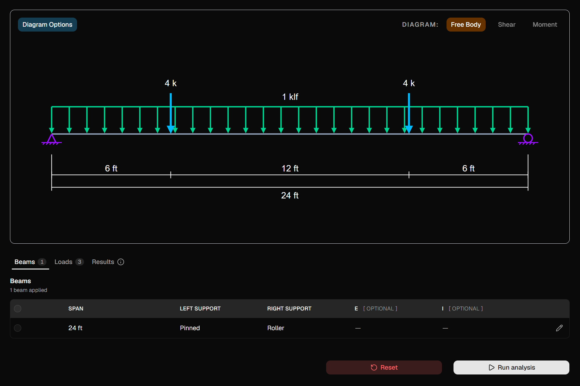
Diagram Panel — Displays the interactive beam diagram. Toggle between Free Body, Shear, and Moment views using the buttons in the upper-right corner.
Input & Results Panel — Contains three tabs: Beams, Loads, and Results.
Screenshot: Main interface showing the diagram panel on the top and the input panel on the bottom.
Getting Started
Step 1 — Define the Beam
Navigate to the Beams tab. The tool currently supports one beam per analysis session.
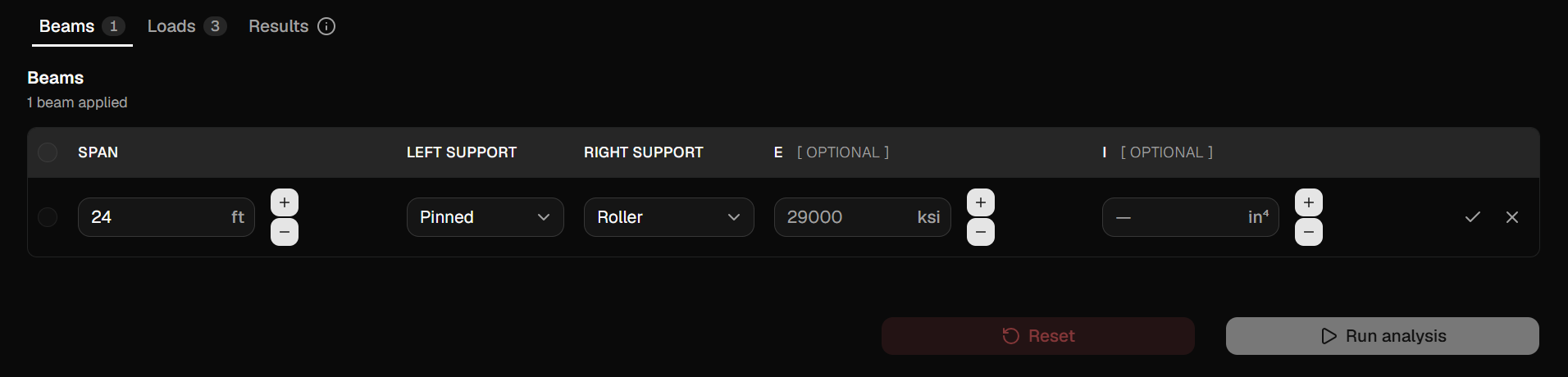
Click the Edit (pencil) icon on the beam row to configure the following properties:
Field
Description
Required
Span
Total beam length, in feet (ft).
Yes
Left Support
Support condition at the left end.
Yes
Right Support
Support condition at the right end.
Yes
E (Modulus of Elasticity)
Material stiffness, in ksi. Defaults to 29,000 ksi if omitted.
No
I (Moment of Inertia)
Cross-section property, in in⁴.
No
Note: E and I are optional and are used only for deflection calculations. They are available on select subscription tiers.
Available Support Types
Fixed — Resists vertical force, horizontal force, and moment (fully restrained).
Pinned — Resists vertical and horizontal forces; rotation is free.
Roller — Resists vertical force only; horizontal translation and rotation are free.
Free — No restraint (cantilever free end).
Click the checkmark icon to save the beam, or the X icon to cancel.
Screenshot: Beam row in edit mode showing span, left support, and right support fields.
Step 2 — Apply Loads
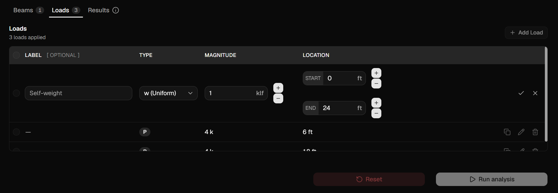
Navigate to the Loads tab. Click Add Load to open a new entry row in the table.
Load Types
Type
Description
Magnitude Unit
P
Point load — applied at a single location.
kips (k)
W (Uniform)
Uniformly distributed load — constant intensity over a range.
kips per linear foot (klf)
W (Triangular)
Triangularly distributed load — linearly varying from zero to a peak.
klf
W (Trapezoidal)
Trapezoidally distributed load — linearly varying between two non-zero intensities.
klf
M
Applied moment — concentrated moment at a single location.
kip-feet (k-ft)
Note: Distributed loads (Uniform, Triangular, Trapezoidal) and Moment loads may require an upgraded subscription tier.
Load Fields
Field
Description
Label
Optional descriptive name (e.g., "Self-weight", "Live Load").
Type
Load type selected from the dropdown.
Magnitude
Load intensity or force value. For Triangular and Trapezoidal loads, both a start and end magnitude are required.
Location
Distance from the left end of the beam, in feet. For distributed loads, both a start and end distance are required.
Click the checkmark to save the load or X to cancel.
Screenshot: Loads table with a uniformly distributed load entry in edit mode.
Managing Loads
Edit — Click the pencil icon on any row to modify an existing load.
Copy — Click the copy icon on a row to duplicate a load. The duplicate is immediately opened for editing.
Delete — Click the trash icon to permanently remove a single load.
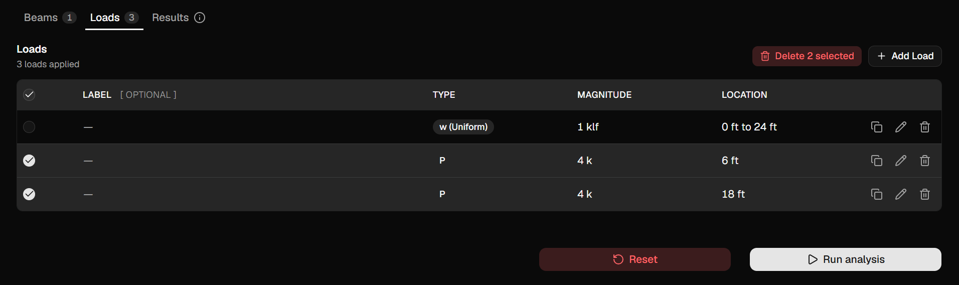
Bulk Actions — Select one or more rows using the checkboxes in the first column, then use the Copy or Delete toolbar buttons to act on the selection.
Editing or adding is limited to one row at a time. All other actions are disabled while an edit is in progress.
Screenshot: Loads table with two rows selected and the bulk "Delete 2 selected" button visible in the toolbar.
Step 3 — Run the Analysis
Once a beam and at least one load are defined, click Run Analysis at the bottom of the panel.
The Run Analysis button is disabled if:
No loads have been applied.
A form row is currently open for editing.
An analysis is already in progress.
While the analysis runs, a spinner is displayed and all inputs are locked. If an error is returned (e.g., an indeterminate or unstable structure), an error message will appear below the action buttons and a red indicator will appear on the Results tab.
Viewing Results
Results Tab
After a successful analysis, navigate to the Results tab to review:
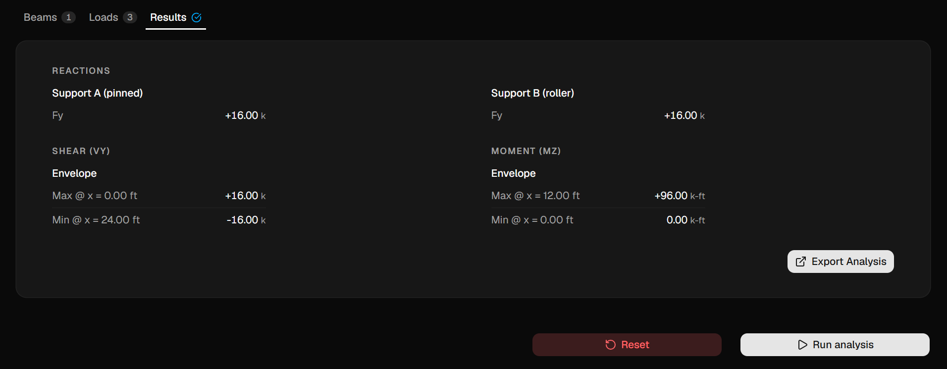
Reactions — Support forces (Fx, Fy) and moments (Mz) at Support A (left) and Support B (right).
Shear Envelope (Vy) — Maximum and minimum shear values and their positions along the beam.
Moment Envelope (Mz) — Maximum and minimum bending moment values and their positions along the beam.
All values are reported with units appropriate to the selected unit system.
Screenshot: Results tab showing reaction values for both supports and shear/moment envelope summaries.
Diagram Panel
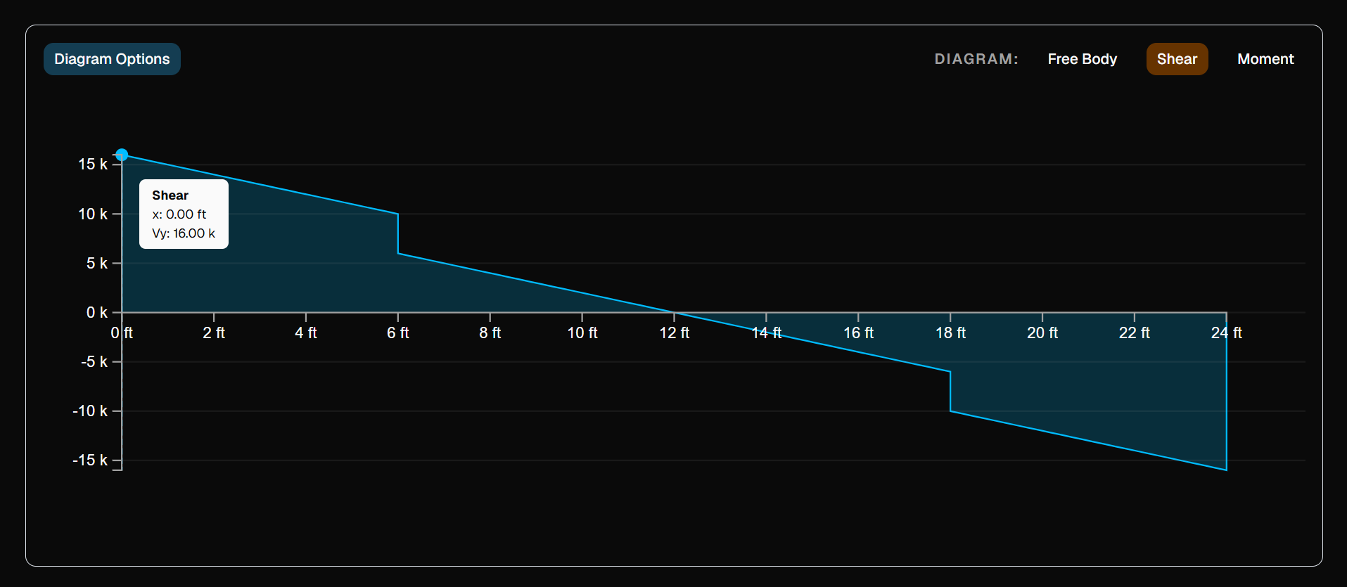
The diagram panel updates automatically after each successful analysis. Use the buttons in the upper-right corner to switch between views:
Diagram
Description
Free Body
Displays the beam geometry, support conditions, and all applied loads. Available at all times.
Shear
Shear force diagram (SFD). Available after a successful analysis.
Moment
Bending moment diagram (BMD). Available after a successful analysis.
Diagram panel displaying the shear force diagram with labeled peak values.
Diagram Options
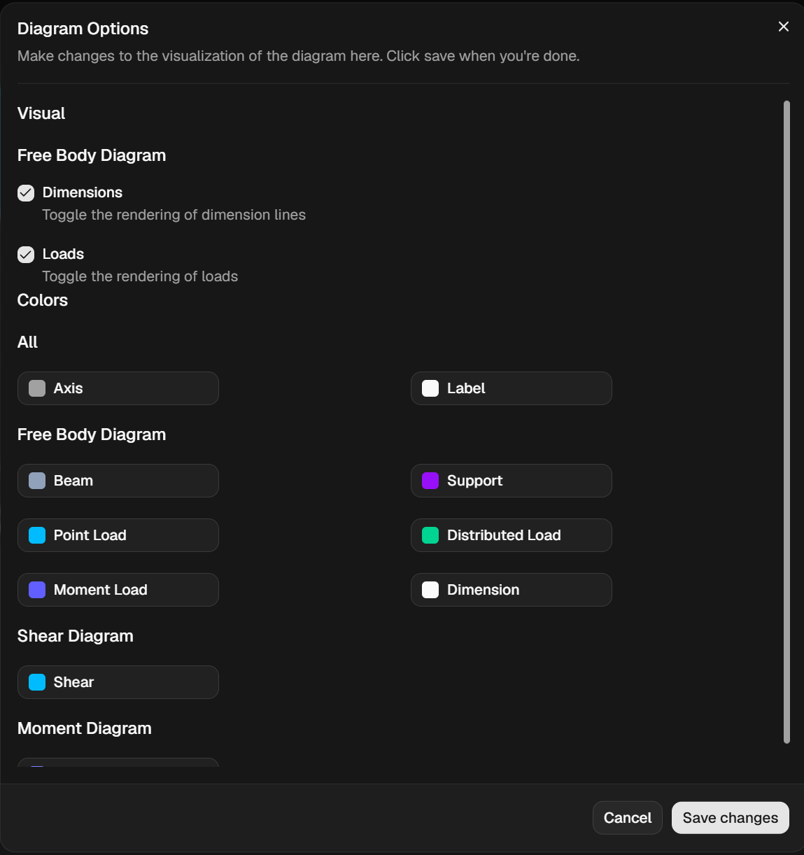
Click Diagram Options (upper-left of the diagram panel) to open the options dialog.
Visual Options
Option
Description
Show Dimensions
Toggles dimension labels on the free body diagram.
Show Loads
Toggles load labels on the free body diagram.
Color Customization
Individual colors for diagram elements (beam, loads, shear curve, moment curve, etc.) can be customized per diagram type using the color pickers in the Colors section. Changes apply immediately upon clicking Save Changes.
Click Cancel to discard any unsaved changes.
Screenshot: Diagram Options dialog showing the Visual and Colors sections.
Exporting the Report
Subscription Required: The Export feature is available on select subscription tiers.
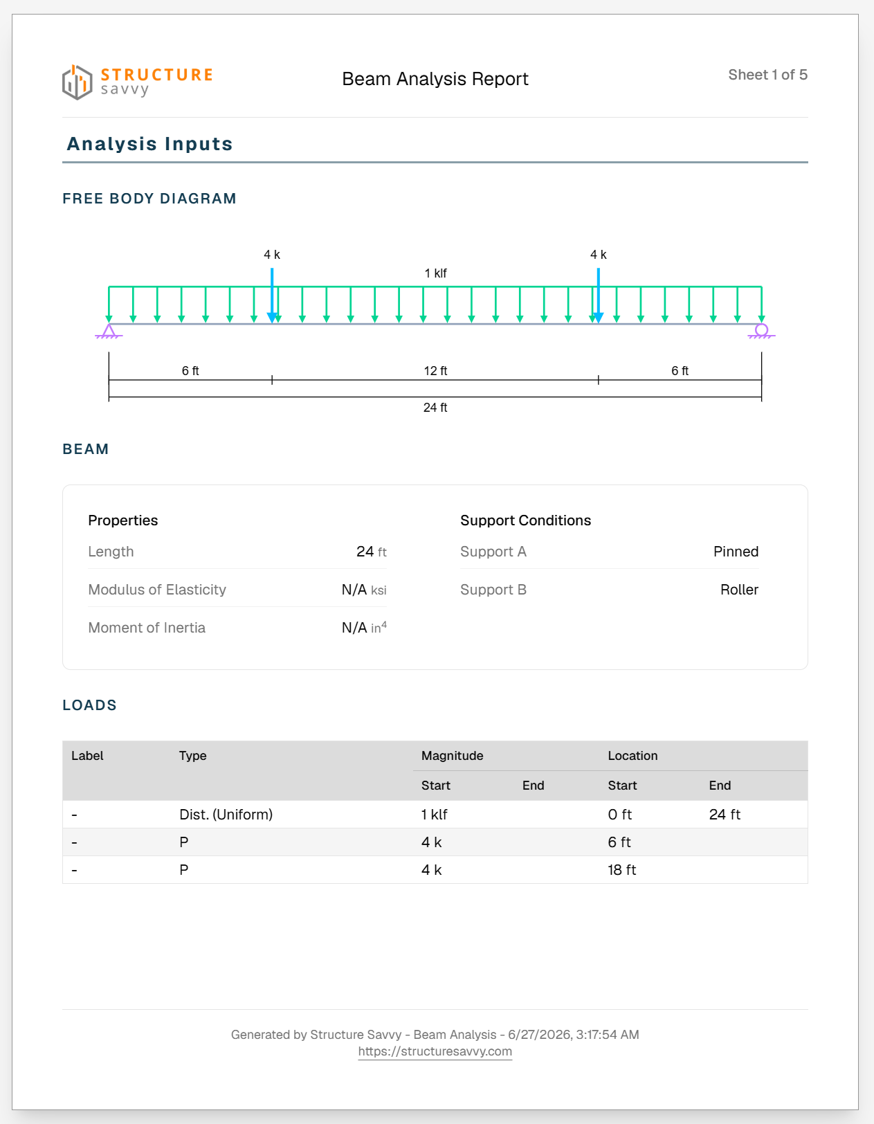
Click Export Analysis in the Results tab to open the print preview in a new browser tab.
The exported report includes:
Analysis Inputs — Beam properties, support conditions, free body diagram, and applied loads table.
Analysis Results — Reaction summary, shear force diagram, bending moment diagram, and reaction values.
Shear & Moment Table — Tabulated V and M values at regular intervals along the beam length.
Shear & Moment Equations — Governing equations for each load case applied.
The report is formatted for standard letter-size paper and can be printed or saved as a PDF directly from the browser's print dialog.
Screenshot: Print preview showing the first sheet with the free body diagram and analysis input table.
Resetting the Analysis
Click Reset to clear all beam properties and loads and restore the tool to its default state. A confirmation dialog will appear before any data is deleted.
Warning: This action cannot be undone. All beam and load data will be permanently cleared.
The Reset button is disabled while an edit is in progress or an analysis is running.
Troubleshooting
"Run Analysis" is disabled and I have loads applied.
Ensure no load or beam row is currently open in edit mode. Click the X icon on any open row to close it, then try again.
The analysis returned an error.
Common causes include:
An unstable or indeterminate structure (e.g., both supports set to Free).
Incompatible support conditions for the given load configuration.
Review the error message displayed below the action buttons and verify that your support types produce a stable, statically determinate system.
The Shear and Moment diagram buttons are grayed out.
These views become available only after a successful analysis has been run. Click Run Analysis to generate results.
Diagram colors appear incorrect after customization.
Open Diagram Options and verify that valid color values are selected. Clicking Cancel in the dialog will revert any unsaved color changes.
The export page displays "No beam analysis found."
SVG diagram data is passed to the export page at the moment you click Export Analysis. If you navigate directly to the export URL, refresh the main analysis page, run the analysis again, and click Export Analysis to retry.
Keyboard & Interaction Notes
Pressing Enter while editing a beam or load row will submit and save the row.
Only one row can be in edit mode at a time. Starting an edit on one row will not automatically close another.
Bulk selection is cleared automatically when a copy or delete action is completed.